
SystemVerilog Configurations and Tool Flow Using SCons (an Improved Make)
Originally presented at DVCon US 2020
Table of contents
Introduction
The motivation for this paper is twofold. First, a few years back one of the authors wanted to implement SystemVerilog configurations with one of the tool vendors but could not get all the pieces quite right. The author tried looking up documentation from the vendor and came up short. Next was a search of the internet only to have the search recommend several papers by none other than the author himself. These papers focused on the basics of configurations but gave no details about any tool-specific setup to use configurations. The authors felt publishing the hooks needed to set up configurations with the primary tool vendors would not be enough content to justify a paper for DVCon. However, while working with each tool vendor to get an initial configurations sample set up, each vendor provided a Makefile to run the tool commands. This leads to the second part of this paper which will introduce SCons as a modern and improved alternative to Make. One of the co-authors has been using SCons on current projects to manage tools and design flow, so it seemed logical to combine configurations (state what is to be implemented) with SCons (execute the implementation).
Configurations
Put simply, configurations define the source used for each instance in a design. For most designs, the configuration is self-implemented based on the design hierarchy and the files provided. However, there are some situations when the source used for a simulation might need to be switched. A common example is switching a behavioral model of an analog block with a spice model for use in an analog-digital mixed simulation, called an AMS or ADMS simulation. Another example is to swap out an RTL model of a component in a large system with its gate version. This is useful for very large designs where full system gate-level simulations can be painfully long1.
Configurations Past and Present
Configurations have been part of Verilog from its inception, they were just called `ifdef macros [1]. The `ifdef
macro has been widely used and is still a significant part of managing design compilation and configuration. They
can be used at a high level to select which files to compile or at a granular level to select between multiple
implementations of design models. `ifdef macros are one of the only ways to selectively configure ports for a
module. This is needed to define power ports for UPF behavioral models that have multiple power ports, something
that is not added automatically by UPF. UPF will auto-imply power ports if there is only one voltage defined for the
model. But we digress, details for UPF behavioral modeling will have to be the subject of another paper. The `ifdef
macro configuration model is applied during compilation, meaning every time a change is needed, the affected design
must be recompiled. Also, note that the `ifdef macro configuration is coded as part of the model.
One of the features added in the Verilog 2001 specification is the generate statement [2]. Generate statements, in a
broad sense, are like `ifdef macros where they can allow a design to selectively choose implementations of design
models. Generate statements are configured using parameters that are set during the elaboration prior to simulation.
Generate statements are used more to configure how the base RTL design will be implemented, such as port and bus
sizes, rather than swapping versions of the design between simulations. Generate can be used to select between
specific instantiations, but as noted above, this must be hard-coded and embedded in the design. There are lots of
usage models that can be applied to generate statements that are beyond the scope of this paper.
The differences between generate statements and `ifdef macros are how and when selections are made. `ifdef
macros are managed by either embedding `define foo in the compiled code or with a +define+foo added to the
compilation arguments. Generate statements are updated during elaboration and are configured using parameters.
Using generate allows for changes to be implemented without recompiling.
Both `ifdef and generate provide unique features not supported by their counterpart. Since Verilog/SystemVerilog
already has these two ways of configuring a design, what does the language configuration feature provide that is not
already present? First, for both `ifdef and generate configurations, the designer must embed these selections in the
code. Second, and more important, the language configuration model allows for defining the source used for specific
instances of a component, and this language configuration model is done external to the design rather than embedded
in the design.
There are some situations where `ifdef macros are the only solution. For example, as previously noted, `ifdef
macros are used within components to enable additional ports for UPF behavioral models that have multiple power
ports. At the system level, `ifdef macros are a reasonable solution to swap the full DUT from RTL to gates in the
TB. However, this approach can have limited flexibility when only part of a DUT is desired to be switched to gates.
This is something that is done with very large designs.
Formal Verilog configurations were added as part of Verilog 2001 and then updated/enhanced with the SystemVerilog generations of the language [NO_PRINTED_FORM] [2], [3]. The primary usage model of configurations is to externally select the source model for instances in the design.
SystemVerilog Configurations
Before discussing SystemVerilog configuration details, it is needful to mention what the focus of this part of the paper is, I.E. what is and what is not in this paper. The motivation of this paper is to show a working model with tool switches to use SystemVerilog configurations. This paper is not going to highlight all the features of configurations such as using configurations to set parameters. Nor will this paper diagram all the specific tool hooks and features. Please refer to section 33 of the IEEE 1800-2017 specification for all the features and details of SystemVerilog configurations [4]. This paper will use a set of model files and configuration settings with a few common variations that will work with all three simulators. This will allow the paper to show a setup that works with the tools discussed in this paper. The objective is to show what files are needed and which switches are needed to apply SystemVerilog configurations to a design using any of the simulators. This paper will not compare tools or features; it is simply a “how-to” paper.
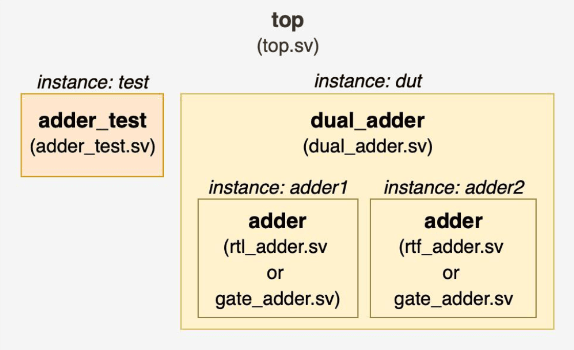
The design used for this paper is diagrammed in Figure 1, below. The code for module top and module dual_adder
is included after the diagram in Example 1 and Example 2.
timeunit 1ns/1ns;
logic a, b, ci;
logic sum1, co1;
logic sum2, co2;
Example 1. top.sv
timeunit 1ns/1ns;
Example 2. dual-adder.sv
To use SystemVerilog configurations, there are two primary definitions that need to be declared, a libmap and a
configuration declaration. These declarations are typically declared in separate files. For this paper, these definitions
will be defined in files named configs.sv and libmap.sv (or libmap_rtl.sv). The libmap declaration specifies
which files are associated with which library. The config file will reference files from the library definitions for use
in the current simulation. As part of experimenting with library options for this paper, the authors used several
different libmaps, but only two are detailed and shown in this paper.
library rtlLib top.sv,
               adder_test.sv,
               rtl_adder.sv,
               dual_adder.sv;

library gateLib gate_adder.sv;
Example 3. libmap.sv
The libmap detailed in Example 3 is a common, simple libmap definition declaring all the primary code (top, test, and
design) in one library, rtlLib in this case. A gate version of the adder is in a second library called gateLib. The
intention of this libmap is to provide a gate adder source model for a replacement to the RTL adder if the configuration
dictates.
An arguably better approach is to divide the design files into three libraries: a top/test library, an RTL library, and a gate library, as shown in Example 4. This alternative style is preferred by the authors as it clearly separates the code into library groups top/test, RTL, and gate which in turn allows for more flexibility and readability.
library rtlLib rtl_adder.sv,
               dual_adder.sv;

library gateLib gate_adder.sv,
                gate_adder_alt.sv;

library testLib top.sv,
                adder_test.sv;
Example 4. libmap_rtl.sv
Along with the library mapping definitions, a configuration needs to be declared. The following three config examples
show a base model configuration that will be used to extend and swap out instance definitions later in this paper. The
configuration declaration begins and ends with the keywords config and endconfig, respectively. The config
statement will declare the name of the configuration as shown in line 1 of Example 5.
config rtl_config;
  design  rtlLib.top;
  default liblist rtlLib;
endconfig
Example 5. rtl_config based on Example 3. libmap.sv
The design statement (line 2) declares the top module of the overall simulation environment and, as shown, may also
specify the library the top module resides in. A config can only have one design statement but may have multiple
top files listed. The default liblist specifies the library or libraries to be searched to find the components of the
design.
The configuration in Example 5 declares that all the files used for the design are in the rtlLib. The next two
configurations are based on using the “preferred” libmap_rtl.sv where the top module and test code is in the
testLib. In Example 6 and Example 7, the design statement declares the top module “top” resides in the testLib.
config rtl_config1;
  design  testLib.top;
  default liblist rtlLib;
endconfig
Example 6. rtl_config1 based on Example 4. libmap_rtl.sv
An interesting observation of Example 6 is that testLib is not listed in the default liblist. The simulation vendors
must infer the testLib from the design statement as a library to search for components not found in rtlLib. In this
case, the adder_test.sv would be the file in the testLib library. Only two of the vendors do this. To model a
configuration that works cleanly with all three vendors and to remove the implied library for searching, the authors
recommend specifying the library in default list as shown in Example 7.
config rtl_config2;
  design  testLib.top;
  default liblist rtlLib testLib;
endconfig
Example 7. rtl_config2 based on Example 4. libmap_rtl.sv
It must be noted here how annoying this default liblist format is. This list is NOT comma-delimited, but space-
delimited. How is this Verilog/SystemVerilog????? Got to love design by committee!!!
As noted previously, the primary purpose/value of SystemVerilog configurations is to substitute instances without the need to modify code or embed selection code in the design files. For the design described in this paper, the following examples will show two ways to use a configuration to swap the module an instance of the adder uses in the DUT. Though there are other ways to swap out a module using configurations, the methods shown in this paper are recommended by the authors.
config cell_config;
  design     testLib.top;
  default    liblist rtlLib testLib;
  cell adder liblist gateLib;
endconfig
Example 8. cell_config with liblist
The configuration modeled in Example 8 declares the top module is found in library testLib. The instantiated
components in the design except for the adder will be found in the libraries specified in the default liblist rtlLib
and testLib. All instances of cell adder will use the module adder found in the gateLib.
config cell_config1;
  design testLib.top;
  default liblist rtlLib testLib;
  cell adder use gateLib.adder;
endconfig
Example 9. cell_config1 with use gateLib.adder
config cell_config2;
  design testLib.top;
  default liblist rtlLib testLib;
  cell adder use gateLib.adder_alt;
endconfig
Example 10. cell_config2 with use gateLib.adder_alt
In the configurations shown in Example 9 and Example 10, the source code for the
cell adder is from the gateLib. By specifying the “use” keyword, the
configuration can call a specific module from this library. This allows for
multiple definitions of a model designated by unique module names to be selected
for use. In these examples, there is a gate module adder and a gate module
adder_alt in the gateLib. Utilizing the “use” keyword, a specific module
is selected for the cell. The module names selected can but do not have to
match the cell name designated in the DUT (in this case adder).
So what is the difference between line 4 in Example 8 and line 4 in Example 9 or Example 10?
The first style using liblist indicates that adder comes from the gateLib
and will match a model name adder. The second using the “use” designator
indicates a specific module from the gateLib to be used. If there is only one
adder module in the library for use with cell adder, then liblist is
sufficient.
The next three examples are a variation of the previous examples. The difference
is that instead of replacing all instances of cell adder, these examples will
replace a specific instance of cell adder. The selection method to designate
the source code for the specific instance is the same as with the previously
referenced examples, Example 8 through Example 10, using liblist or use to
select the source code from a specific library.
config inst_config;
  design   testLib.top;
  default  liblist rtlLib testLib;
  instance top.dut.adder2 liblist gateLib;
endconfig
Example 11. inst_config with liblist
config inst_config1;
  design testLib.top;
  default liblist rtlLib testLib;
  instance top.dut.adder2 use gateLib.adder;
endconfig
Example 12. inst_config1 with use gateLib.adder
config inst_config2;
  design testLib.top;
  default liblist rtlLib testLib;
  instance top.dut.adder2 use gateLib.adder_alt;
endconfig
Example 13. inst_config2 with use gateLib.adder_alt
Note the difference between these config examples and Example 8 through Example
10 is the keyword instance rather than cell. It is important to note that based
on the code setup for this paper, one of the vendors requires the configs.sv be
compiled last for the use clause to work. This is not a big deal and there may
be a vendor switch to remove this requirement but at the time of writing this
paper, a switch has not yet been found.
Tool Specifics to Compile and Simulate Configurations
The primary point of the paper is to document how to simulate configurations with the SystemVerilog simulators. The three simulators available to the authors are from Cadence, Mentor, and Synopsys (alphabetical order.) The intent of the paper is not to compare or contrast these vendors, but simply to show the setup for each tool to simulate configurations.
Cadence Configuration Setup
The authors used the Cadence Xcelium simulator to compile and simulate the
configuration experiments for this paper. The example below shows the Xcelium
xrun switches used.
Example 14. Cadence Xcelium compile and simulate
Notes regarding the xrun command line:
- The
-libmapswitch specifies the configuration library forxruncompilation/simulation. - The
-compcnfgswitch specifies the configuration file used forxruncompilation/simulation. - The
configs.svshould not be included in the source code.ffile. If it is, the simulation will still work but will issue lots of warnings. - The
-topswitch specifies which config from theconfigs.svfile will be used to specify the top unit for simulation.
For reference, the source_code_cadence.f file is listed in Example 15.
Example 15. source_code_cadence.f file
The full Makefile used for the testing with Cadence Xcelium is listed in Appendix A: Makefile.cadence.
Mentor Configuration Setup
The Mentor Questa setup uses a two-step flow. The first step is to compile, and the second step is to simulate.
The compile step specifies the libmap using the -libmap switch with the vlog
command.
Example 16. Questa compile
The only difference between the source code file source_code.f used here and the
one used for the Cadence command line is that this source code file includes the
configs.sv file (compare Example 15 and Example 18). Also, in this source code
file (Example 18), the configs.sv file is listed last as noted in the discussion
above regarding the “use” option in a configuration.
The second step is to simulate the design. The Questa command line to simulate the compiled design is shown in Example 17.
Example 17. Questa simulation
The argument to vsim is the top design, which for a configuration is defined in
the configuration itself. Thus, for Questa vsim, the command is simply vsim
followed by the selected configuration name.
Notes regarding this Example:
- The
-coption indicates command line rather than interactive mode. - The
-dowill run all and exit automatically with the-coption. These commands can be placed in a file as shown in Appendix D: Full SCons and Configurations Example, sub-section K: run_all.sim.
The source code file used for the compile step is shown in Example 18.
Example 18. source_code.f file
Note the source code file shown in Example 18 is used by both the Mentor Questa setup and the Synopsys VCS setup which is detailed in the next section.
The full Mentor Makefile used for this paper is in Appendix B: Makefile.mentor.
Synopsys Configuration Setup
The Synopsys VCS flow is also a two-step flow separating the compilation from the simulation.
Example 19. vcs compile
The VCS vlogan compile command uses the following two switches to compile a
configuration for simulation. Note the configs.sv is included in the
source_code.f file.
-diag libconfig-libmap libmap_rtl.sv
Example 20 shows the vcs simulation command for simulating with a selected
configuration.
Example 20. vcs simulate
Notes regarding the vcs command:
- The selected configuration is noted after the "
-R". - The
-diag libconfigis optional but gives good information. - The
-debug_accessis optional.
The run_vcs.do file referenced in the vcs simulation command is listed in
Example 21.
Example 21. run_vcs.do file
Finally, a library reference file is also needed for vcs to run. This file is
called synopsys_sim.setup and contains the list of libraries declared in the
libmap files. This file resides in the directory where the vcs simulation is run
from and is referenced by the VCS tool.
WORK    > DEFAULT
DEFAULT : work
rtllib  : rtlLib
gatelib : gateLib
testlib : testLib
Example 22. synopsys_sim.setup file
The Synopsys Makefile used for the experiments in this paper is in Appendix C: Makefile.synopsys.
Advanced Concepts for a Future Paper
Using the library maps and the configuration declarations for the example design, the adder module can successfully be configured to use either the RTL version or the gate-level version of the module across each tested simulator. The examples also showed how to select an alternative gate-level module version that is named different from the cell instantiation. Other features not discussed in the paper include:
- Setting parameter in configuration
- Setting a hierarchical configuration for a subsection of a design
- Nested configurations
- Configurations to specify details of generic interconnects
SCons
The remainder of this paper discusses possible approaches for extending SCons to compile and simulate SystemVerilog code. The Makefiles used in the previous section work, but even with the simple configuration presented, they have already grown complex and difficult to manage, with lots of repeated code. This provides a natural candidate for converting to an SCons script. For brevity, inline example code will only be provided for a single vendor. A complete example using each major vendor is contained in Appendix D: Full SCons Example. The examples will remain relatively generic, but the completed scripts will be capable of replicating the configuration Makefiles, and these replications will be presented next to the Makefiles in their respective appendix. This section is based on a similar tutorial on the SCons wiki but has been heavily adapted to be specific to SystemVerilog and its nuances [5].
What is SCons?
SCons is an open-source software construction tool [6]. It is an improved, cross-platform substitute for GNU Make. Some of the benefits include:
- Configuration files are Python scripts, providing the full power of the Python programming language to solve build problems.
- Automatic dependency tracking.
- Detects source changes by MD5 signature (optionally, can be configured to detect by traditional timestamp).
- Improved support for parallel builds (like
make -j, but works regardless of directory hierarchy). - Great support for hierarchical builds that can match the hierarchy of a chip development project.
- Designed to be cross-platform, so a single script can be used on Linux and on Windows if needed.
- Built-in support for C, C++, D, Java, Fortran, Yacc, Lex, Qt, and SWIG, and building TeX and LaTeX documents. Support for additional languages is straightforward.
- Uses a self-contained environment configuration separate from the user’s Unix environment which makes debugging more consistent – anybody who runs the script will have the same set of environment variables and flags set.
- Unifies compiling across a team by extracting all common functionality into a base file that can be imported into each individual project.
The SCons executable is typically installed system-wide and build configurations
are placed in a file named SConstruct. When the scons command is invoked in a
directory, it will search for an SConstruct file by default.
A Simple SystemVerilog Builder, and its Evolution to a Tool
SCons uses Python objects named builders to compile software across different programming languages. Each built-in language (listed above) has a builder capable of compiling the code for that language. SCons can be extended with additional builders to add support for more languages. This section will outline the process of creating a builder for SystemVerilog.
Start with the Command Line
Starting with a single input file, rtl_adder.sv, the compile command "vlog rtl_adder.sv" creates a work library, which contains several collateral files.
SCons needs a target file to latch onto, and the file work/_lib.qdb is a good
choice for this2. This command makes a good starting candidate for implementing
in SCons, starting with a Command() action.
Command Wrapper
import os
env =
envExample 23. A simple command wrapper and SConstruct file
This Python code does two things. First, it sets up the construction environment
and copies the system path into it, so the tools are available to use3. Second,
it creates a Command() builder which will execute the vlog command when scons is
invoked at the command line. The first major benefit of SCons can be seen with
this configuration: file modification detection. Invoking scons will compile
rtl_adder.sv, but only if it detects a change to the file since the last time
scons was invoked. If nothing has changed, scons will report that the target is
up to date and exit. If the project is a single file, this is a great solution,
but it is not very reusable as both the work library name and the source file
are hard-coded.
Simple Builder
One step above a Command() action is a Builder(). A Builder lets us pass in the
command line argument as an action, then call it at a later point with the
source files.
import os
vlogbld =
env =
envExample 24. A simple builder and SConstruct file
This builder specifies a suffix and a src_suffix, so they can be left off the
call to the builder (this is not required). Within the call to the Vlog builder,
test files were added by the authors to the source list as well, so now a change
to any one of them will cause scons to recompile. The builder is more portable
now, but it still needs to be manually pasted into each SConstruct that needs
it.
First Version of a Tool
Tools are Python modules or packages that SCons uses to modify an environment.
They can alter environment variables, add builders, or otherwise modify an
environment to prepare for any required tasks. They are a convenient location to
store SCons code that will be shared by a team. The only SCons requirement to be
a proper tool is to define two functions, exists() and generate(). The first
method is used by SCons to determine if all the conditions to use the tool are
met. This method can be used to check that the needed executables are available
in the current PATH. The generate() method is what modifies the Environment.
from SCons.Script import *
##########################
# Builders
##########################
_vlog_builder =
"""Add Builders and construction variables to the Environment."""
['Vlog'] = _vlog_builder
return 1Example 25. An initial framework for an SCons tool
This tool provides the same functionality as the builder previously implemented.
Tools are saved in a different location. By default, SCons will look in the
folder site_scons/site_tools/ for extra tools. Create the folder hierarchy
site_scons/site_tools/questa and place the above code in a file named
__init__.py (this is how Python declares packages). To use the tool in an
SConstruct file, modify it like this:
import os
env =
envExample 26. SConstruct file using the tool defined in Example 25
This directory could be shared in version control and made available to each project. This would allow each team member to use the same compile commands, which will reduce bugs.
Prettying It Up
There are still some issues with this tool: the work library name is still
hard-coded, there is no way to specify additional command-line arguments, and it
would be nicer to be able to use the run.f file list instead of manually
specifying each source file. Additionally, the important follow-up step of
simulating the design after compiling is still missing.
Scanners
By default, SCons will only track changes for the files specified in the source
list. This means that if the project source files are contained in a .f file
list, SCons will not monitor them for changes. However, SCons has a class named
Scanner that can be used to process files for additional dependencies. A Scanner
object can be configured to search .f files and .sv files (packages, libraries)
for additional dependencies and allow SCons to track every SystemVerilog file in
the project automatically. This is one feature that is an improvement from Make.
######################################################################
# SCANNERS:
# Scanners to parse .f files and .sv files for dependencies
######################################################################
f_re = re
sv_re = re
include_re = re
contents = node
sv_files = sv_re
sv_files = [sv for sv in sv_files]
f_files = f_re
while f_files:
for f in f_files:
# The following line is used to expand any environment variables
# in the filepath using the custom SCons environment. This will
# catch any variables declared in the SConstruct.
ef = subprocess
if os:
current_dir = os + '/'
contents = env
sv_files
f_files
sv_files
f_files
results = []
for f in env:
results
return results
contents = node
includes = include_re
starting_dir = + '/'
if includes == []:
return [node]
results = []
for inc in includes:
if os:
results
return env
svscan =
fscan =
Example 27. .f and .sv file scanner objects and functions
In the SCANNERS section, there are two simple scanners. The first one,
ffile_scan, searches a .f file for other .f files and for .sv files. It will
continue looping through any .f file it finds until it is left with a list of
only .sv files. It then passes the list of .sv files over to svfile_scan, which
searches each file for additional files that been included using `include. When
the scan completes, scons will have a full dependency list of every file in the
design4. If any file changes, calling scons will cause a re-compile. Otherwise,
scons will report that the design is up to date.
Environment Variables and Pseudo-Builders
######################################################################
# BUILDERS:
######################################################################
### vlog
action = []
for s in source:
if os[1] == '.f':
action
action
action
action
action
return ' '
"""A pseudo-Builder wrapper for the vlog executable."""
_vlog_builder =
result = _vlog_builder
env
return result
### vsim
action = []
action
action
action
return ' '
"""A pseudo-Builder wrapper for the vsim executable."""
_vsim_builder =
result = _vsim_builder
env
return resultExample 28. Tool builders and pseudo-builders for compiling and simulating
In the BUILDERS section, there is a second builder to handle simulating. The
builders now use a generator function to create an action on the fly instead of
using a hard-coded action. This gives a lot of flexibility in what command the
builder uses. In this example, the builder loops through all the source files
passed into the call to the builder and add a -F flag if it is a .f file. This
way, .sv files and .f files can be mixed in the source list. The hard-coded work
library name was also replaced with an environment variable and added a few
other environment variables to help make the command generic and configurable by
the user:
- The
env['VLOG']variable points to thevlogexecutable. This could be used to configure for specific versions ofvlogor to swap for an alternate tool (valog, for example). - In the
generate_vlog()andgenerate_vsim()methods, the work library is added using the${SIM_DIR}${WORK}variable combination. The target now points to the log file that will be generated by each command. - The
env['VLOG_ARGS']andenv['VSIM_ARGS']variables are available so the user can add any additional arguments needed to the commands. - The
${SIM_DIR}variable allows the option to place all generated files in a separate directory. In this example, it will move the work library and the log files to a separate directory.
There are three different ways to access environment variables. If needed
outside of a string, looking up the variable in the env dictionary is
appropriate (env['VLOG']). Inside a string, if the variable has white-space
both before and after it, the variable can be accessed using just a $ sign -
'$VLOG' would return the same thing. If the variable is used within another
part of the string, wrapping the variable with curly braces allows it to be
replaced with its value properly (${SIM_DIR}vlog.log). Additionally, this
allows the option of special modifiers to be used to access different parts of
the variable such as dir for the directory of the file and file for just the
file name. The scons man page details several other modifiers [7].
The actual builders for Vlog and Vsim are wrapped in pseudo-builders. A
pseudo-builder allows for extra functionality to be added to a builder such as
modifying the source or target list, adding additional dependencies, or handling
side-effects. The full power of Python is available within a pseudo-builder. In
this example, each pseudo-builder adds a call to Clean(). This allows for
specifying additional files that should be removed when scons -c is called at
the command line. By default, scons will remove the target file only. Now it
will remove the work directory and the .done file in addition to the log files.
Generate Method
######################################################################
# TOOL FUNCTIONS:
# generate() and exists() are required by SCons
######################################################################
"""Add Builders and construction variables to the Environment."""
= env
= env
env
env
env
env
return TrueExample 29. Tool required functions: generate() and exists()
In the generate() method, the environment is set up:
- This is a good location to set up the executable variables.
- By appending the two scanners created in Example 27 to the environment, they
will automatically be called when
sconsdetects a source file matching the filetypes they specified in theirskeyslist. - The
SetDefault()method allows for specifying default values for any needed environment variables. A user can then overwrite them as needed and use the defaults the rest of the time. A variable can also be directly set (as was done for the executable variables), which will not allow the user to change it. - To add a pseudo-builder to the environment, use the
AddMethod()function instead of assigning the method to theenv['BUILDERS']dictionary.
Aliases, Dependencies, and AlwaysBuild
The SConstruct file now looks like this:
import os
env =
vlog = env
env
vsim = env
env
Example 30. SConstruct file using the tool defined in Example 27 through Example 29
In the Environment() initializer, alternate variables are set for SIM_DIR and
WORK. The call to Vlog can now use these variables in its target. The source
file list has been replaced with the .f file. Now that there are multiple
targets, it is convenient to define an Alias(). Aliases allow for one or more
targets to be called using a single target alias name. That alias can then be
used as a dependency in future targets. In this example, the defined alias
'compile' points to the Vlog target. The Vsim target uses 'compile' as its
dependency, which will ensure the design is always compiled before simulating. A
'sim' alias is declared, then AlwaysBuild() is called on it to ensure a
simulation every time scons is invoked, instead of stopping after the first
time. Alternatively, a phony target name could be used that doesn’t correlate to
any generated files (such as 'simulate'). Because nothing would be created
matching the target, scons would attempt to build it every time it is called.
The issue with this approach is if a file or folder does exist with the same
name, scons will exit with an error, or delete the file. For example, if the
target had been set to a phony 'sim', there would have been a conflict with the
SIM_DIR variable where the work library is placed. It is better to be explicit
about the target, then use Alias() to make it more user-friendly.
At this point, a call to scons will compile the design then start a simulation.
Repeated calls to scons without modifying any of the source code will just
simulate. A target can also be called explicitly: scons compile will not
simulate with either compile or report up to date.
Hierarchical Builds
The tool is in a good state for individual module-level projects, but it has room for improvement at the chip level. SCons supports hierarchical builds, which can significantly reduce compile time at the chip level by compiling multiple modules simultaneously and by only recompiling what has been updated. To do this, SCons using a file (typically named SConscript) placed in a project subdirectory that acts as an extension of the construction environment. Within the SConstruct file, the compile target can be replaced with an SConscript function call like so:
import os
env =
vsim = env
env
Example 31. SConstruct file using an SConscript file for the compile step
This registers the file src/SConscript and will include its content when
building. The contents of that file are the compile targets removed from the
SConstruct file:
vlog = env
envExample 32. The SConscript file referenced in Example 31
This concept can be significantly expanded such that a chip project could have a
separate SConscript file for each submodule that is responsible for compiling
the module, and all of them are linked together at the top-level SConstruct. All
the submodule compile calls can be built in parallel, and only the submodules
that have modified code will be recompiled on successive calls to compile.
There is one issue with the scanners and using SConscript files that the authors
have not been able to reconcile yet. Even though SConscript will look for files
relative to the directory its file is in (by default), the scanners appear to
scan only from the location of SConstruct. One method around this issue is to
have a default location where all .f files are placed that the scanner can start
from, and each file then links to a .f file in the associated SConscript
directory.
Advanced Concepts for a Future Paper
This introduction to SCons shows the basic steps needed to build a capable build tool and use it in an SConstruct file. There are many advanced concepts that can improve performance further. Some examples include:
- Adding command-line arguments to modify program flow dynamically.
- Using the
Help()method to dynamically generate help text for the user. - Creating Python-based targets that can dynamically generate TCL files used in a simulation.
- Using aliases to create conditional regression targets that modify a regression test list based on provided conditions.
- Using the built-in builders to compile C code needed for a chip simulation.
- Demonstrating a complex hierarchy of SConscript files and build tools.
Conclusion
This paper introduced the basics of SystemVerilog configurations and then explained how use configurations to specify a unique file definition for a cell declared inside a design. With these definitions, the paper presented a set of model files and configuration settings that will work with the simulators available to the authors, and successfully demonstrated SystemVerilog configurations functioning across the simulators.
The Makefiles provided by the simulator vendors provided a baseline to introduce the concept of SCons as a newer, better way to manage design flow. The second part of this paper presented the basics for using SCons with SystemVerilog, and how it is an improvement over using Makefiles. A guide was presented that demonstrated the steps to creating a functional SCons tool extension to allow SCons to compile and simulate SystemVerilog code. While this tool is complete, it is still generic. It has support for modifying command-line arguments for the supported executables, but it doesn't handle any advanced management of command-line arguments. It is likely that within a company, each design team will have their own application of SCons and SystemVerilog tool extensions. This will allow each team to customize the builders to their specific environments, projects, and tools. Using the guide presented in this paper, the reader will be able to write these SCons builders and streamline project tool flows.
References
Appendix: Source Code
The full code used throughout the paper to demonstrate configurations and SCons is found in the following repository: https://github.com/DillanCMills/configuration_scons_example
Footnotes
-
These gate models need a wrapper to account for required setup time between RTL to gate data paths. Feel free to contact the authors regarding this concept if needed. ↩
-
A Directory can be used as a target in SCons, but because there is no data to monitor, the target will be rebuilt every time SCons is invoked, which removes SCons' ability to automatically track dependencies. Any file generated by the command is a good candidate for a target. ↩
-
SCons recommends hard-coding every necessary variable into the construction environment to guarantee portability instead of copying variables from the system environment. The authors recommend copying from the system environment when it would be difficult to hard code the value needed. ↩
-
These scanners are provided as an example - the regex used by them may not be comprehensive. For typical configurations, they will work, but if the user has anything complicated, the configurations might need to be adjusted to match the use-case. ↩